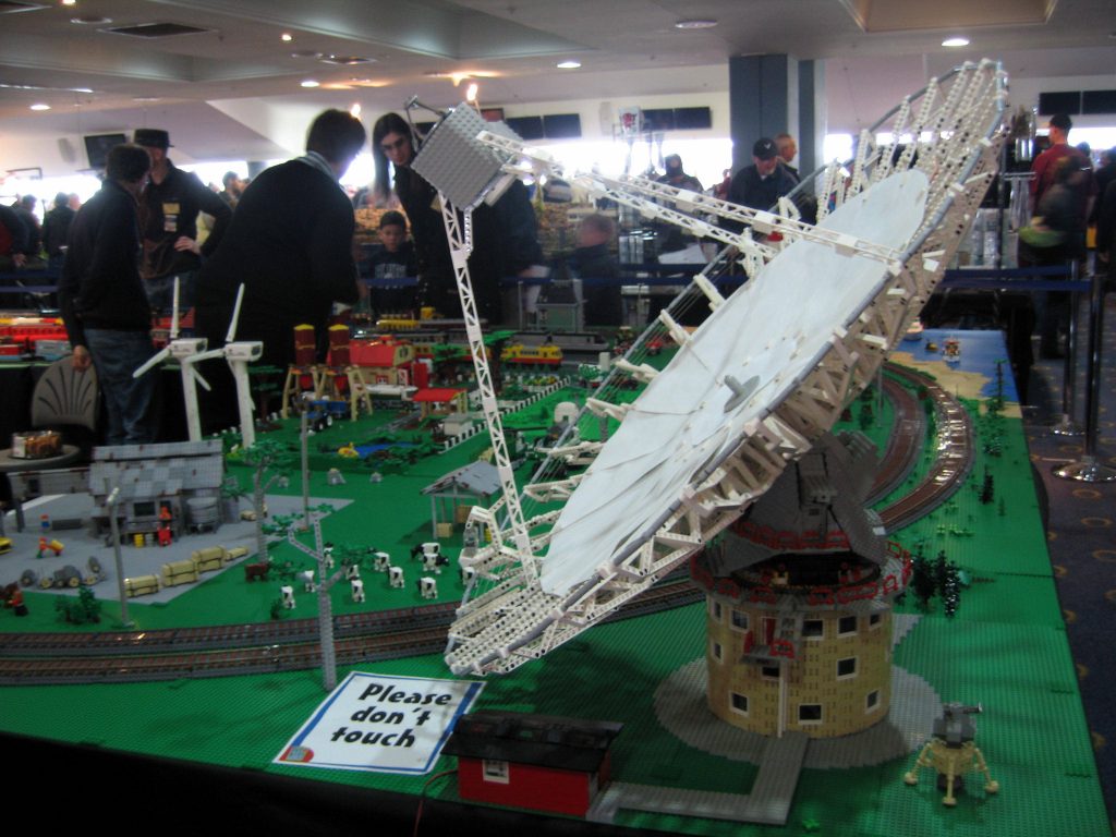
The “Melbourne Star” is an observation wheel in Melbourne’s Docklands area, giving an unparalleled view of the city. So what’s that got to do with my Southern Star Wheel? I’m glad you asked!
The current wheel (bottom, incomplete) was built after problems were discovered with the original design (top). You can see the hub & spoke design is significantly different. So it was decided the new attraction needed a different name, so it wouldn’t be forever tarnished with the memory of the first failed version.
And that is why my MOC, based on the original design, is named “Southern Star”, rather than “Melbourne Star”. If you want to see a model of the “Melbourne Star”, check out The Brickman.
So much for introductions. As you can see, both wheels are based on the 7-point “Commonwealth Star” depicted on the lower hoist quarter of the flag of Australia. Six of the seven points represent the original six states of Australia, while the seventh represents the territories.
Anyway, that meant I had to come up with a way to create a symmetrical 7-point star using LEGO, which is not a trivial task. After many hours of trial and error, I came upon the approximation that
sin(Ï€/14) = 2/9
And with that knowledge I was able to come up with a hub composed of 14 equal segments.
Once I had a solid hub, I needed 7 points. This I worked out by finding a point length that resulted in a circumference divisible by 21. This was because the circumference had to approximate a circle, and each section had to carry a single observation car, so it would be much easier if they were all the same length. It worked out that a circumference of 21 x 15 studs was almost perfect.
And next I needed to fit a section between each pair of points that resulted in approximately the correct angle between all 21 segments. This also proved to be more difficult than expected, but after lots of failed attempts, I eventually ended up with this.
Purists please ignore the thin plastic spacers I used in the centre join.
The ends are attached using longitudinal pins, attached via rubber mounts to allow some movement.
It’s starting to get pretty heavy now, so the next order of business is a strong mounting frame.
Each side has a vertical mast which supports most of the load, and 2 diagonal braces to hold it upright. Some tricky connections where the 3 come together at the top.
It’s all made to be assembled as easily as possible at shows.
On to the cars. The trickiest thing about these was that I wanted them to look as much like the real pods as possible, and they also had to rotate to remain vertical.
Purists again please ignore the plastic spacers used as washer to minimise friction.
The design I ended up with was actually too short for minifigs to have hair, so this wheel has the unusual restriction that riders must be bald!
The cars are attached using an axle connector at each end.
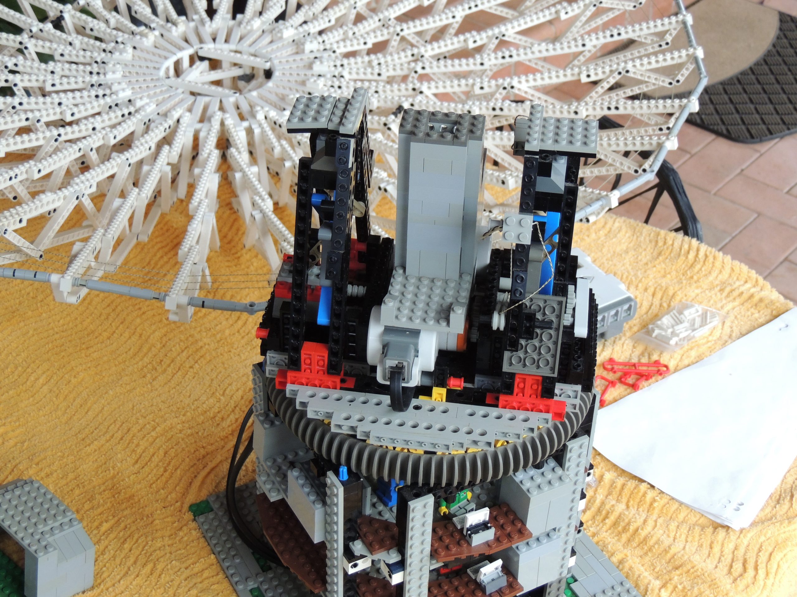
All we need now is a way to drive it. This is what I came up with (upside down!) – the main requirement was to have some pressure on the driving frame so it could maintain solid contact with the wheel which is not perfectly circular.
In the end, it is probably way more complex than it needed to be, and is definitely not as reliable as I’d like. But it generally works OK.
So in conclusion, there’s quite a few things I’d change if I was building it today:
The drive mechanism
The car design
The main frame joint
But I’m not, so I won’t.
And here’s the obligatory setup video, filmed in reverse & sped up 5x.
This story begins in 2011, the year of the radio telescope’s 50th anniversary. That was when I decided to build the model, hopefully having it ready for the anniversary on 31st October that year.
Alas, circumstances meant that didn’t happen, but in 2012 work began. I had to choose a scale, but I also knew I’d be limited by how I chose to build the main components, so this was really a balancing act. I built a “circle” using 12L axles & #3 axle joiners. That resulted in a dish about 0.5m in diameter, but I couldn’t come up with a way to make a decent looking round structure at that scale.
So I ended up using 2 x 12L axles between each joiner, approximately doubling the diameter to just over 1m, resulting in a scale of about 1:60. The bonus was, that is in my “acceptable minifig scale” range!
But that also meant it was going to be big, so I knew my big MOC chops would be tested. Hence the protruding tongue.
Of course the other main thing that determined the scale was how I chose to build the round structure. This was actually determined y my choice of window – in order to get the right number of windows, the structure ended up being almost exactly the right size for my chosen scale!
Unfortunately, to look good I had to put the shutter holders on the inside, and because the inside is concave, they had to be filed a little to fit. If you consider that heresy, maybe you should be reading a different blog…
So onto construction of the dish itself, and it was no simple matter to get the curved shape, keeping it strong & light at the same time. I used my old favourite technique: trial & error, and I was pretty happy with the result. Each pair of struts joined by 2 12L axles is a single unit, and there are 16 units to make the full circle.
Three strands of non-stretch braided fishing line are used to hold them together – there was no way clutch power would be able to do that.
Holding them together at the centre was not trivial either – I ended up using hinge plates between each strut pair, and a combination of beams to provide a strong mount point. I wanted to be able to tilt this without needing any other support, so this had to be strong. This mount went through several iterations before arriving at the final version.
Note that only 8 of the strut pairs are actually attached directly to the centre mount – every other pair is only held on by those hinge plates (top & bottom), and the axles at the rim. So I could have halved the number of struts and still had enough support, but I don’t think it would have looked as good.
On to the supporting structure. The real telescope is supported by a main central column, but I already knew I wasn’t going to be able to balance the dish, so that wasn’t an option. I ended up with 4 simple frames, one on each side, with some bracing. Then I re-used the slew ring from my CC-2800 crane, employing the droid wheel and a race of 2×2 technic wheels. This provided plenty of support for the rotating platform.
On the platform I built 2 well braced A-frames to mount the the tilting mechanism. Under one A-frame is the asimuth (slew) gearing, the elevation (tilt) gearing is under the other. The 2 NXT motors are mounted centrally, in opposing directions, topped of with the dish access door and central support column.
Next came the tilting mount. I had to make this super strong, because not only did it have to support the weight of the dish, but also some fairly decent shear forces when it was tilted. I also wanted to make it as heavy as possible, to reduce strain on the tilt mechanism.
Strength is provided by internal Technic beams, and weight is provided by 13 2x6x2 weight bricks. It is still nowhere near heavy enough to balance the dish.
To attach the dish to the mount, the beams on the bottom locate on the blue axle-pins you can see in the photo above, with the mount frames passing through the centre of the dish. Then the 2 black “hands” (also seen above) rotate to grab the top beams.
A centre block is then inserted to hold the “hands” in place. This block also carries a circle of paper to cover the centre section of the dish.
We’re getting close now, but I had to come up with a 6-sided box for the focus cabin. Inside there’s a bunch of Technic to get the shape right, unfortunately adding fairly significantly to the weight. But I am happy how it turned out. I was also able to add the small dish on top.
It is mounted on 3 legs, one of which has a lift for easy access to the focus cabin. I didn’t even try to make it movable, but it does at least tilt as the dish moves.
Building a shed to hide the NXT was a welcome (i short) relief. The cables run through a conduit that could be described as a path, then up the centre to the motors. This means it cannot turn continuously, but in reality it would never need to.
Why red? Simply because I have more 1xN bricks in red than any other colour. And it matched the doors.
Lastly, I decided to add some interior detail. I’ve no idea why, you can’t see it from outside anyway. There’s a few figs, some computer screens, and lots of knobs & dials.
There’s even a model of the dish on the ground floor!
And we can see proof that figs work late into the night…
And finally we get to the hardest part – the programming! It is programmed in NXC, using the excellent Bricx Command Centre, by Mark Overmars & John Hansen. It also uses the Bluetooth library “BTLib” by Daniele Benedettelli.
It consists of 2 main programs, “master” that runs on the NXT in the red shed and actually controls the dish, and “remote” that runs on a 2nd NXT and can be used to control “master” remotely via Bluetooth.
The programs share UI code, and the current position of the dish is displayed on both a couple of times per second.
In order to follow the path of astronomical bodies, I had to decide whether to calculate positions on-the-fly, or use lookup tables. I decided on the latter, as the calculations are not trivial, and that was not the main focus of the MOC anyway.
So I created a spreadsheet in which I can enter the details of the object to follow, and spit out data I can put into a files that are compiled then downloaded (or is that uploaded???) to the NXT.
Anyway, I zipped up a bunch of stuff I figured you programming types might be interested in, you can download it here.
Finally I’ve had to admit defeat, and remove the old site pages. This is due to the fact that I have no motivation to update the Joomla software they were on, and it doesn’t run well on PHP 5.6, which is now required for my WordPress blog. So adieu, BRE, it was fun while it lasted!
Some of my really old LEGO projects were documented on my LUGNET page, and some others are documented in this blog. I may get motivated to update it all some time in the future, but that’s currently looking unlikely.
Nothing alcohol related, I assure you. Just dementia.
Now where was I? Oh yeah, the Pirates also did a few covers, and here’s one of them. Another classic penned by the inimitable Paul Kelly. Ah yes, now I remember where I got the title for this post…
This is a live recording of “Alliance”, another band I played bass with in the 80s. It’s a version of the Toto classic “Hold the Line”. I think it was probably recorded through the mixing desk, on my 4-track, probably at the Wheatsheaf Hotel, but I can’t be sure. Would have been mid-late 80s.
Unfortunately I chose to put the drums & bass on separate tracks, which meant the guitar & keys are sharing a track. But I was young and didn’t know what I was doing. Now I’m just old and don’t know what I’m doing…
LEGO®,Technic®, Mindstorms® are trademarks of The LEGO Group of companies, which does
not sponsor, authorise or endorse this site. Please visit the official LEGO site here.